
Motor Torque and Balancing Considerations
One of the goals of our wheel drive system has been to maximize the available torque. This is partly to ensure there is enough correction force available to allow balancing to work, and partly to compensate for the fairly high mass of our current robot. This has influenced our motor choice: we use MakeBlock 42BYG stepper motors which have a 1.7 Amp rating per coil, which is quite a bit higher than motors we previously used.
We use the DRV8825 motor controller, and are careful to get carrier boards with real TI DRV8825 chips, not clones.
To maximize the possible rotation speed, and torque, we operate the controllers in single step mode. According to the DRV8825 specs, in this mode the controller is always sending about 71 percent of the available current to each coil.
In order to have the full maximum rated current sent to the motors, we thought we should adjust the output of the motor controllers to 1.7 A / .71 = 2.4 Amps. So when the controller sent 71% of this, the full 1.7 A would get to the motor coils.
In retrospect, this configuration breaks a couple of rules. Initially we didn’t put heat sinks on the DRV8825’s despite the current, either 1.7 or 2.4 A, depending how you look at it, being above the 1.5 A threshold for additional heat dissipation. Also, if you believe that you need to use the 2.4 value for limit calculations (which is implied by later test results) we were also over the 2.2 Amp maximum for the DRV8825.
Despite this we were able to get the robots to balance for short periods of time, but they weren’t very stable.
To investigate, we worked on 3 sub-projects:
- Bench testing of motor performance at various current settings, and rotation speeds
- Analysis of the torque requirements of balancing
- Analysis of the torque capacity of the motors
A) Motor Performance
To help with motor testing, we implemented an MQTT command we could send to the robot to set one or both motors directly to specified speed(s). When we tried this out with our original configuration, we found that after a few minutes of running continuously at a constant speed, the motors would pause, and sometimes act erratically, and even reverse directions. Our suspicion is that this is due to defensive action by the motor controller when it detects overheating, over-voltage, over-current or something similar. (We’re going to check to see if the fault pin on the motor controller is being asserted at some point.) We added heat sinks on the bottom of the DRV8825 carrier board where the heat exits after being drawn through the circuit board, but eventually used heat sinks stuck directly on the DRV8825 chips. These get very hot in almost any operation, so it seems like a good place for them.
We attempted some systematic testing, considering these factors:
- front panel open or closed (heat dissipation factor)
- the Vref value, which controls the maximum current sent to the motors
- the motor drive voltage. We had been using more than the nominal voltage
- heat sink config. Ended up always using a heat sink right on DRV8825
- motor speed in test. Speed is a misnomer. See discussion below
We eventually just tested on one wheel, because changing Vref on the DRV8825 obscured by the ESP32’s console cable is a pain.
Speed: What we call speed is inverted, and low numbers are faster wheel rotation. Technically, the number is the count of 20 usec clock ticks between sending a step command to the motor controller. Each step results in a 1.8 degree rotation of the wheel. We used 3 speeds:
- 800 - slow
- 500 - medium
- 300 - fast
Details of our testing are in the DRV-test-cases.??? spreadsheet, but the summary is that we needed to reduce the Vref to .9 volts to avoid motor pauses and unreliability. To have a little safety margin, we decided to us a Vref of .85 which means a maximum current of twice that, 1.7 Amps. This matches motor current rating of 1.7 Amps, assuming we’re ignoring 71% factor implied by using single stepping. Our test results suggest that the using the 71% factor in the max current calculation isn’t valid.
The threshold for needing heat sinks is 1.5 A, and our 1.7 A (ignoring the 71% factor) is slightly over that. Hopefully the heatsinks directly attached to the DRV8825 chip can handle this.
It would be nice to do more testing to test more speeds, and cases without heat sinks.
B) Torque needs for Balancing
When you think of the robot’s wheel motors trying to counteract the tilting of the robot, there are two sources of torque that we need to overcome: 1) The torque caused by the pull of gravity on the robot’s centre of mass 2) The torque caused by the angular momentum of the tilting action.
We were able to calculate the first of these, using these formulas:
torque = radius * force = radius * mass * acceleration
We considered the torque to be applied at the centre of mass, located roughly half the distance from the wheel axle to the top of robot. We weighed various components, but excluded the symmetrical motors from the mass being torqued.
When the robot is tilted from vertical by an angle theta, the acceleration perpendicular to the robot’s vertical axis is: (gravity accel) * sin( theta)
Example: tilt = 5 degrees radius = .074 metres mass = 1.153 Kg
torque = radius * mass * accel = 0.074 * 1.153 * (9.81 * sin(5 degrees)) = .085322 * 9.81 * .087155 = 0.073 Kg-m
The torque values for a range of tilt angles is shown in the spreadsheet torqueCalcs1.??? . Torque-1 through Torque-6 are the same torque value expressed in different units, as defined in the second line of column titles. We’re working mostly in Kg-m, in the Torque-1 column.
We haven’t yet figured out how to calculate the torque needed to overcome a given angular momentum. There are additional parameters, angular velocity, and possibly angular acceleration, so we can’t just create another column in our chart. More research is needed.
C) Torque Capacity
We wanted to understand how much torque our motors can exert, in practical terms, but couldn’t make much sense of motor specifications, which each seem to use different units. So we decided to measure how much weight the motors could lift against gravity. We devised an attachment to the wheel axle that is a rod that acts like an extension to a diameter of the wheel. At the end of it a customized paperclip is suspended, and washers of various weights are added to determine the motor’s maximum lifting capacity. The motor controller’s ENA pin is set so that the coils are magnetized, but we don’t do STEP pulses until the test starts. As a result, the rod is ‘clenched’ in position while the washers are being arranged, etc.
In the static torque measurement, the rod is initially positioned horizontally. When the motor is started, it must immediately lift the full weight of the washer load against the force of gravity. We’ve done one test in this configuration. It used a ‘speed’ of 500, and was able to lift 96.2 grams.
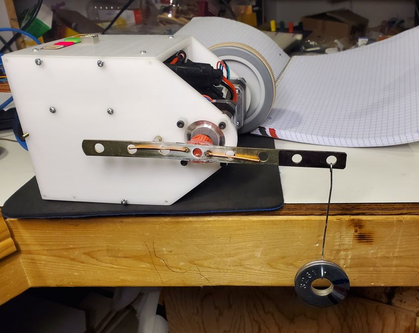
In the dynamic measurement, the rod is initially positioned vertically. When the motor is started, the motion of the suspension point is almost horizontal, with almost no load due to the washers. As the rod rotates, the effective load increases, and when it’s horizontal, the full weight is being lifted. We’ve done one test in this configuration, again at speed 500. The maximum load that could be lifted to the point where the rod was again vertical was 206.2 g.
These results are summarized at the bottom of the first sheet in torqueCalcs1.???. The green shading in the chart indicates the angle range where the motor’s static torque can overcome the torque due to tilt, ignoring momentum. The blue shading expands this for the torques measured using the dynamic technique.